-
Machine tools
-
Machine tool accessories
-
Welding, cutting equipment
-
OEM Machined parts, components

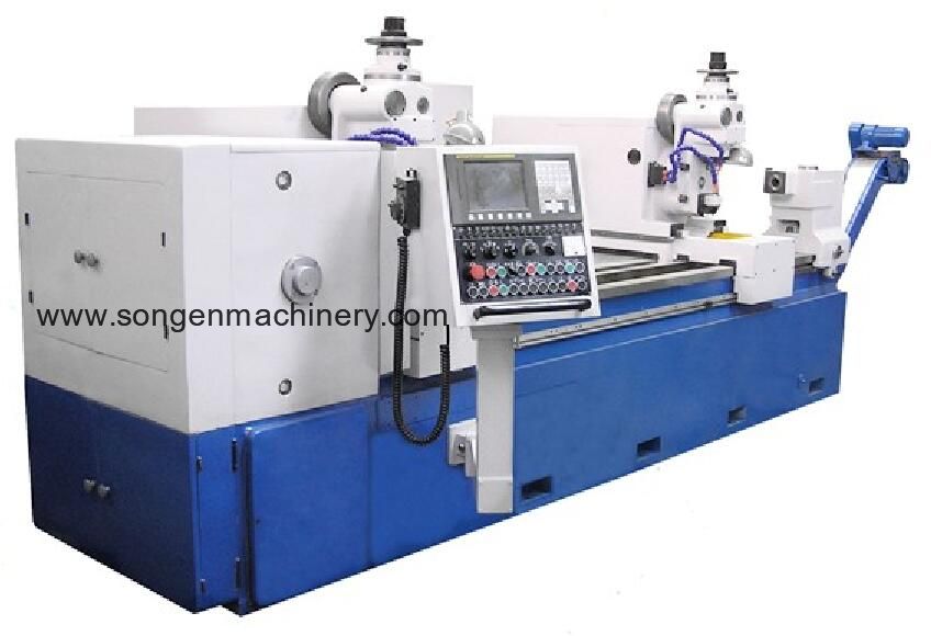
1. This CNC-SSM160X2500 CNC controlled double-head spline shaft milling machine is widely used to hob and mill the straight-tooth spline shafts and the externally engaging cylindrical gear shafts. It can milling both spline ends on a shaft such as heavy duty vehicles's bridge shell assemblies. Mainly it is used to hob the involute splines on both ends of the middle bridge shells and the rear bridge shells on the heavy duty vehicles;
2. Fanuc Oi CNC system, PLC controllers and α12/3000 and α14/3000 servo motors are equipped on this spline shaft milling machine to control and drive the two milling heads to perform the positionings and feedings on the longitudinal direction and the cross direction and the shifts of the sequency of the processes in machining;
3. After workpiece set-up, the milling heads can perform automatically the following processes in sequency:
Step 1: Milling heads perform the rapid cross traverse, feeding and positioning;
Step 2: Milling heads perform the rough longitudinal feeding;
Step 3: Milling heads rapidly return;
Step 4: Milling heads perform the rapid cross traverse, feeding and positioning;
Step 5: Milling heads perform the fine longitudinal feeding;
Step 6: Milling heads rapidly return;
Step 7: Hydraulic chuck and taistock loose to release the finished parts.
4. The cross feedings and swivels of two milling heads can be controlled simultaneously or separately on customer's request;
5. Single- or double-cycle can be selected as the automatic processing cycles. Each step in the processing cycle can be performed independently;
6. The two milling heads rotation direction are opposite and perform upmilling or downmilling;
7. Hand cutter shifting device on this machine presets the cutter and prolong its service life.
| No. | Specifications | Model CNC-SSM160X2500 | |
| 1 | Max. milling diameter | 160 mm | |
| 2 | Distance between centerlines of two milling heads | 1700 - 2300 mm | |
| 3 | X Milling head right travel | 100 mm | |
| 4 | Y Milling head left travel | 500 mm | |
| 5 | Max. workpiece length | 2500 mm | |
| 6 | Machine center height | 370 mm | |
| 7 | Number of teeth processing | 24 - 30 | |
| 8 | Max. milling module | 6 mm | |
| 9 | Hobbing cutter speeds | 60 - 200 RPM, Stepless | |
| 10 | Distance between workpiece centerline and cutter centerline | 70 - 145 mm | |
| 11 | Max. hobbing cutter diameter | 130 mm | |
| 12 | Max. hobber cutter length | 110 mm | |
| 13 | Hobbing cutter arbor diameters | 27, 32, 40 mm | |
| 14 | Hobbing cutter spindle bore taper | MT #4 | |
| 15 | Tailstock quill taper | MT #5 | |
| 16 | Tailstock quill travel | 50 mm | |
| 17 | Rapid traverse | Cross | 6000 mm/Minute |
| Longitudinal | 6000 mm/Minute | ||
| 18 | Main motor | 7.5 KW, 2400 RPM | |
| 19 | Hydraulic unit motor | 1.1 KW, 1400 RPM | |
| 20 | Longitudinal servo motor | Output torque | 40 N.M |
| Max. speed | 3000 RPM | ||
| 21 | Cross servo motor | Output torque | 12 N.M |
| Max. speed | 2000 RPM | ||
| 22 | Coolant pump motor | Motor power | 450 W |
| Flow rate | 200 L/Minute | ||
| 23 | Machine overall size | 5160 x 2518 x 1794 mm | |
Machining accuracy:
| No. | Item | Value |
| 1 | Equal division accumulated error | 0.035 mm |
| 2 | Parallellism between keyway's side and workpiece's centerline | 0.03 mm |
| 3 | Parallellism between two sides of each keyway | 0.03 mm |
| 4 | Surface roughness | Ra. ≤3.2 μm |


 Horizontal lathes
